eScience Lectures Notes : Display Devices
Slide 1 : Display Technologies
Display Technologies
Video Displays
Slide 2 : Display Devices
Display Devices
Former lesson : importance of computer graphics in today world
As seen in the first lecture, there is a widespread recognition
of the power and utility of computer graphics in virtually all fields, a broad
range of graphics hardware and sofware are available. We will begin by having
a look at the displays device.
Slide 3 : Display Technologies
Cathode Ray Tubes (CRTs)
|
|
-
Most common display device today
-
Evacuated glass tube
-
Heating element (filament)
-
Electrons attracted to focusing anode cylinder
-
Vertical and Horizontal deflection plates
-
Beam strikes phosphor coating on front of tube
|
CRTs, or video monitors, are the most common output device
on computers today.
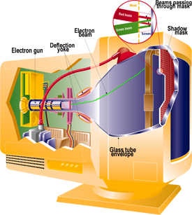
The figure below illustrates the basic structure of a CRT.
A CRT is an evacuated glass tube, with a heating element
on one end and a phosphor coated screen on the other.
When a current flows through this heating element, called a filament, the conductivity
of the metal filament is reduced due to the high temperature. This cause electrons
to pile up on the filament, because they can not move as fast as they would
like to. Some of these electrons actually boil off of the filament.
These free electrons are attracted to a strong positive charge from the outer
surface of the focusing anode cylinder (sometimes called an electrostatic lens).
However, the inside of the cylinder has a weaker negative charge. Thus when
the electrons head toward the anode they are forced into a beam and accelerated
by the repulsion of the inner cylinder walls in just the way that water is speeds
up when its flow though a smaller diameter pipe. By the time the electrons get
out they're going so fast that they fly past the cathode they were heading for.
The next thing that the electrons run into are two sets of weakly charged deflection
plates. These plates have opposite charges, one positive the other negative.
While their charge is not strong enough to capture the fast moving electrons
they do influence the path of the beam. The first set displaces the beam up
and down, and the second displaces the beam left and right. The electrons are
sent flying out of the neck of the bottle, until they smash into the phosphor
coating on the other end of the bottle.
The impact of this collision on the out valence bands of the phosphor compounds
knocks some of the electrons to jump into the another band. This causes a few
photons to be generated, and results in our seeing a spot on the CRT's face.
Slide 4 : Vector Displays
Vector Displays
|
|
-
Oscilloscopes were some of the 1st computer displays
-
Used by both analog and digital computers
-
Computation results used to drive the vertical and horizontal axis
(X-Y)
-
Intensity could also be controlled (Z-axis)
-
Used mostly for line drawings
-
Called vector, calligraphic or affectionately stroker
displays
-
Display list had to be constantly updated
(except for storage tubes)
|
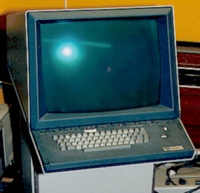
Tektronix 4014
|
CRTs were embraced as output devices very early in the
development of digital computers.
There close cousins, vacuum tubes, were some of the first
switching elements used to build computers. Today, the CRT is a the last remaining
vacuum tube in most systems (Even the flashing lights are solid-state LEDs).
Most likely, oscilloscopes were some of the first computer graphics displays.
The results of computations could be used to directly drive the vertical and
horizontal displacement plates in order to draw lines on the CRT's face. By
varying the current to the heating filament the output of the electron beam
could also be controlled. This allowed the intensity of the lines to vary from
bright to completely dark.
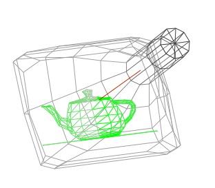
These early CRT displays were called vector, calligraphic or affectionately
stroker displays. The demonstration above gives some feel for how they worked.
By the way, this demo is an active Java applet. You can click and drag your
mouse inside of the image to reorient the CRT for a better view. Notice the
wireframe nature of the displayed image. This demo is complicated by the fact
that it's a wireframe simulation of a wireframe display system. Notice how the
color of the gray lines of the CRT vary from dark to light indicating which
parts of the model that are closer to the viewer. This technique is called depth-cueing,
and it was used frequently on vector displays.
The intensity variations seen on the teapot, however, are for a different reason.
Eventually, the phosphors recover from their excited state and the displaced
electrons return back to their original bands. The glow of the phosphor fades.
Thus, the image on the CRT's face must be constantly redrawn, refreshed, or
updated. The two primary problems with vector displays are that they required
constant updates to avoid fading, thus limiting the drawn scene's complexity,
and they only drew wireframes.
Slide 5 : Raster Displays
Raster Displays
 |
-
TV boomed in the 50s and early 60s
(they got cheap)
-
B/W TVs are basically oscilloscopes
(with a hardwired scan pattern)
-
Entire screen painted 30 times/sec
-
Screen is traversed 60 times/sec
-
Even/Odd lines on alternate scans
(called fields)
-
Interlace - a hack to give
-
Smooth motion
on dynamic scenes
-
High Resolution
on static scenes
-
Optimize bandwidth
|
During the late 50s and early 60s, broadcast television,
really began to take off. It had been around for a while, but it didn't become
a commodity item until about this time. Televisions are basically just oscilloscopes.
The main difference is that instead of having complete control over the vertical
and horizontal deflection, a television sweeps its trace across the entire face
in a regular fixed pattern (the actual details are slightly more complicated,
but that's the jist of it). This scanning pattern proceeds from the top-left
of the screen to the bottom-right as shown in the diagram.
The final result is that the entire screen is painted once every 1/30th of a
second (33 mS) in USA and once every 1/25th in europe or in Australia.
Televisions were mass produced and inexpensive. For a
computer to paint the entire screen it needs only to synchronize its painting
with the constant scanning pattern of the raster. The solution to this problem
was to add a special memory that operated synchronous to the raster scanning
of the TV, called a frame buffer.
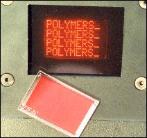
While televisions were cheap, memory wasn't. So there was a long period where
the patterns were scanned out of a cheap high-density read-only memories, called
character generators. The trick was to use a single 8 bit code to specify an
8 by 12 character pattern from the ROM, and with a few addressing tricks one
could build a nice display (80 by 25 character) with only 2 kilobytes of memory.
Thus the era of the CRT-terminal was born.
Slide 6 : Character Based Frame Buffer
Raster Display
 |
In a raster display the path of the electron beam
is hardwired. The computer must synchronize its "painting" of
the screen with the scanning of the display. The computer only controls
the intensity of the color at each point on the screen. Usually a dedicated
section of memory, called the frame buffer, is used to store these intensity
variations.
|
The simulation above is a Java applet that simulates the
scanning of a raster display. Move the CRT wireframe (by clicking and dragging)
in order to get a better feel.
There were a few attempts at building systems with downloadable or programmable
character generators. And a few systems added an extra byte to specify the foreground
and background colors of the character cell. Lots of tank/maze arcade games
in the 70's worked this way. But by the late 70's and early 80's the price of
memory started a free-fall and the graphics terminal was born. In a later lecture
we'll go into a lot more detail about the notion of a framebuffer an how it
is fundamental to modern computer graphics.
Slide 7 :
Color Video
Color Video
Delta Electron Gun Arrangement
|
Color CRTs are much more complicated
-
Requires precision geometry
-
Patterned phosphors on CRT face
-
Aligned metal shadow mask
-
Three electron guns
-
Less bright than monochrome CRTs
|
In-line Electron Gun Arrangement
|
Color CRT's are more complicated than the simple monochrome
models summarized before. The phosphors on the face of a color CRT are laid
out in a precise geometric pattern. There are two primary variations, the stripe
pattern of in-line tubes shown on the left, and the delta pattern of delta tubes
as shown on the right.
Within the neck of the CRT there are three electron guns, one each for red,
green, and blue (the actual beams are all the same color-- invisible). There
is also a special metal plate just behind the phosphor cover front face, called
a shadow mask. This mask is aligned so that it simultaneously allows each electron
beam to see only the phosphors of its assigned color and blocks the phosphor
of the remaining two colors.
The figure shown above shows the configuration of an example in-line tube. On
page 44 of Hearn & Baker you'll see a similar diagram for a delta electron
gun configuration
A significant portion of the electron beam's energy strikes the mask rather
than the phosphors. This has two side effects. The shadow mask has to be extremely
rigid to stay aligned with the phosphor patterns on the CRT face. The collision
of electrons with metal mask causes the mask to emit some of it absorbed energy
as electromagnetic radiation. Most of this energy is in the form of heat, but
some fraction is emitted as x-rays. X-rays can present a health hazard. This
wasn't a large problem for television because the intensity of the x-ray radiation
falls off quickly as you move away from the screen. However, computer monitors
are supposed to be viewed from a short distance. This health concern along with
the high voltages and power dissipations of CRTs has motivated the development
of new display technologies.
For more information on CRTs check out the following links:
The History
of the Cathode Ray Tube
The Scoop on CRTs
History
Slide 8 : Cathode Ray Tubes Summary
Raster Display Summary
 |
Disadvantages
-
Requires screen-sized memory array
-
Discrete spatial sampling (pixels)
-
Moire patterns result when shadow-mask and dot-pitch frequencies
are mismatched
-
Convergence (varying angles of approach distance of e-beam across
CRT face)
-
Limit on practical size (< 40 inches)
-
Spurious X-ray radiation
-
Occupies a large volume
Advantages
-
Allows solids to be displayed
-
Leverages low-cost CRT H/W (TVs)
-
Whole Screen is constantly updated
-
Bright light-emitting display technology
|
Slide 9 : Comparison CRT / LCD
Comparison CRT / LCD
Cathode Ray Tubes
|
Liquid Crystal Displays (LCDs)
|
Advantages
-
Fast repsonse (high resolution possible)
-
Full color (large modulation depth of E-beam)
-
Saturated and natural colors
-
Inexpensive, matured technology
-
Wide angle, high contrast and brightness
|
Advantages
-
-
Light weight (typ. 1/5 of CRT)
-
Low power consumption (typ. 1/4 of CRT)
-
Completely flat screen - no geometrical errors
-
Crisp pictures - digital and uniform colors
-
No electromagnetic emission
-
Fully digital signal processing possible
-
Large screens (>20 inch) on desktops
|
Disadvantages
-
Large and heavy (typ. 70x70 cm, 15 kg)
-
High power consumption (typ. 140W)
-
Harmful DC and AC electric and magnetic fields
-
Flickering at 50-80 Hz (no memory effect)
-
Geometrical errors at edges
|
Disadvantages
-
High price (presently 3x CRT)
-
Poor viewing angle (typ. +/- 50 degrees)
-
Low contrast and luminance (typ. 1:100)
-
Low luminance (typ. 200 cd/m2)
|
|
|
Slide 10 : Liquid Crystal Displays (LCDs)
Liquid Crystal Displays (LCDs)
Currently, the most popular alternative to the CRT is the Liquid Crystal Display
(LCD). LCDs are organic molecules that, in the absence of external forces, tend
to align themselves in crystalline structures. But, when an external force is
applied they will rearrange themselves as if they were a liquid. Some liquid
crystals respond to heat (i.e. mood rings), others respond to electromagnetic
forces.
When used as optical (light) modulators LCDs change polarization rather than
transparency (at least this is true for the most popular type of LCD called
Super-twisted Nematic Liquid crystals). In their unexcited or crystalline state
the LCDs rotate the polarization of light by 90 degrees. In the presence of
an electric field, LCDs the small electrostatic charges of the molecules align
with the impinging E field.
The LCD's transition between crystalline and liquid states is a slow process.
This has both good and bad side effects. LCDs, like phosphors, remain "on"
for some time after the E field is applied. Thus the image is persistent like
a CRT's, but this lasts just until the crystals can realign themselves, thus
they must be constantly refreshed, again, like a CRT.
The book Hearns & Baker is a little confusing in describing
how LCDs work (pp. 47-48). They call the relaxed state the "On State"
and the excited state the "Off State". Their statement is only true
from the point of view of the pixels when the LCDs are used in a transmissive
mode (like on most laptops). The opposite is true when the LCDs are used in
a reflective mode (like on watches).
Slide 11 : Reflective and Backlit LCDs
Reflective and Backlit LCDs
Rather than generating light like a CRTs, LCDs act as
light values. Therefore, they are dependent on some external light source. In
the case of a transmissive display, usually some sort of back light is used.
Reflective displays take advantage of the ambient light. Thus, transmissive
displays are difficult to see when they are overwhelmed by external light sources,
whereas reflective displays can't be seen in the dark.
You should also note that at least half of the light is
lost in most LCD configurations. Can you see why?
Slide 12 : Active Matrix LCDs
Active Matrix LCDs
Active Matrix LCDs (aka Thin Film Transistor (TFT))
The LCD's themselves have extremely low power requirements.
A very small electric field is required to excite the crystals into their liquid
state. Most of the energy used by an LCD display system is due to the back lighting.
It was mentioned earlier that LCD's slowly transition back to their crystalline
state when the E field is removed. In scanned displays, with a large number
of pixels, the percentage of the time that LCDs are excited is very small. Thus
the crystals spend most of their time in intermediate states, being neither
"On" or "Off". This behavior is indicative of passive displays.
You might notice that these displays are not very sharp and are prone to ghosting.
Another way to building LCD displays uses an active matrix. The individual cells
are very similar to those described above. The main difference is that the electric
field is retained by a capacitor so that the crystal remains in a constant state.
Transistor switches are used to transfer charge into the capacitors during the
scanning process. The capacitors can hold the charge for significantly longer
than the refresh period yielding a crisp display with no shadows. Active displays,
require a working capacitor and transistor for each LCD or pixel element, and
thus, they are more expensive to produce.
TFT displays
Many companies have adopted Thin Film Transistor (TFT)
technology to improve colour screens. In a TFT screen, also known as active
matrix, an extra matrix of transistors is connected to the LCD panel - one transistor
for each colour (RGB) of each pixel. These transistors drive the pixels, eliminating
at a stroke the problems of ghosting and slow response speed that afflict non-TFT
LCDs. The result is screen response times of the order of 25ms, contrast ratios
in the region of 200:1 to 400:1 and brightness values between 200 and 250 cd/m2
(candela per square metre).
The liquid crystal elements of each pixel are arranged so that in their normal
state (with no voltage applied) the light coming through the passive filter
is 'incorrectly' polarised and thus blocked. But when a voltage is applied across
the liquid crystal elements they twist by up to ninety degrees in proportion
to the voltage, changing their polarisation and letting more light through.
The transistors control the degree of twist and hence the intensity of the red,
green and blue elements of each pixel forming the image on the display.
TFT screens can be made much thinner than LCDs, making them lighter, and refresh
rates now approach those of CRTs as the current runs about ten times faster
than on a DSTN screen. VGA screens need 921,000 transistors (640 x 480 x 3),
while a resolution of 1024 x 768 needs 2,359,296 and each has to be perfect.
The complete matrix of transistors has to be produced on a single, expensive
silicon wafer and the presence of more than a couple of impurities means that
the whole wafer must be discarded. This leads to a high wastage rate and is
the main reason for the high price of TFT displays. It’s also the reason
why in any TFT display there are liable to be a couple of defective’ pixels
where the transistors have failed.
There are two phenomenon which define a defective LCD pixel:
A 'lit' pixel, which appears as one or several randomly-placed red, blue and/or
green pixel elements on an all-black background, or
a 'missing' or 'dead' pixel, which appears as a black dot on all-white backgrounds.
The former is the more common and is the result of a transistor occasionally
shorting on, resulting in a permanently 'turned-on' (red, green or blue) pixel.
Unfortunately, fixing the transistor itself is not possible after assembly.
It is possible to disable an offending transistor using a laser. However, this
just creates black dots which would appear on a white background. Permanently
turned on pixels are a fairly common occurrence in LCD manufacturing and LCD
manufacturers set limits - based on user feedback and manufacturing cost data
- as to how many defective pixels are acceptable for a given LCD panel. The
goal in setting these limits is to maintain reasonable product pricing while
minimising the degree of user distraction from defective pixels. For example,
a 1024x768 native resolution panel - containing a total of 2,359,296 (1024x768x3)
pixels - which has 20 defective pixels, would have a pixel defect rate of (20/2,359,296)*100
= 0.0008%.
TFT panels have undergone significant evolution since the days of the early,
Twisted Nematic (TN) technology based panels.
Slide 13 : Plasma Display Panels
Plasma Display Panels
|
|
-
Promising for large format displays
-
Basically fluorescent tubes
-
High-voltage discharge excites gas mixture (He, Xe)
-
Upon relaxation UV light is emitted
-
UV light excites phosphors
-
Large viewing angle
|
-
Less efficient than CRTs
-
Not as bright
-
More power
-
Large pixels (~1mm compared to 0.2mm for CRT)
-
Ion bombardment depletes phosphors
|
 |
Plasma display panels (PDPs) are essentially a matrix of very small fluorescent
tubes with red, green, and blue phosphors. As in ordinary tubes, a discharge
is initiated by a high voltage which excites a mixture of inert-gases such as
He and Xe. Upon relaxation, ultra-violet (UV) radiation is generated which excites
the phosphors.
PDPs provide a large viewing angle since the phosphors emit light uniformly.
A 40-inch PDP typically consumes about 300 W whereas the peak brightness is
only 1/3 of that of a CRT consuming about half the power. Sealing and vacuum
pressure support problems apply to PDPs as well, requiring thicker glass as
the screen is enlarged. In addition, the discharge chambers have pixel pitches
of more than 1 mm which makes it difficult to construct high-definition television
(HDTV) and work-station monitors. By contrast, TFTLCDs, CRTs and FEDs may have
pixel pitches as small as 0.2 mm.
Slide 14 : Field Emission Devices (FEDs)
Field Emission Devices (FEDs)
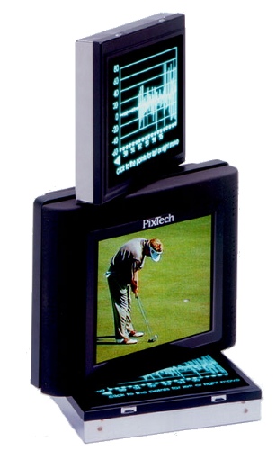
PixTech |
 |
-
Works like a CRT with multiple electron guns at each pixel
-
Uses modest voltages applied to sharp points to produce strong E
fields
-
Reliable electrodes proven difficult to produce
-
Limited in size
-
Thin, and requires a vacuum
|
Field Emission Display: a display technology which use
vacuum tubes (one for each pixel) with conventional RGB phosphors.
Slide 15 : Digital Micromirror Devices (DMDs)
Digital Micromirror Devices (DMDs)
(aka Digital Light Processing / DLP / commercial name)
(A Micro-Optical Electromechanical Device - MOEMS - for Display Applications)
|
Texas Instruments
|
-
Microelectromechanical (MEMs) devices
-
Fabricated using VLSI processing techniques
-
2-D array of mirrors
-
Tilts +/- 10 degrees
-
Electrostatically controlled
-
Truly digital pixel
|
|
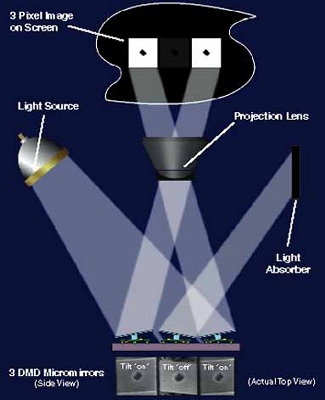
Three Mirrors Project Image
Incoming light hits the three mirror pixels. The
two outer mirrors that are turned on reflect the light through the projection
lens and onto the screen. These two "on" mirrors produce square,
white pixel images. The central mirror is tilted to the "off"
position. This mirror reflects light away from the projection lens to
a light absorber so no light reaches the screen at that particular pixel,
producing a square, dark pixel image. In the same way, the remaining mirror
pixels reflect light to the screen or away from it. By using a color filter
system and by varying the amount of time each of the DMD™ mirror
pixels is on, a full-color, digital picture is projected onto the screen.
|
-
Suitable only for projection displays
-
Gray levels via Pulse-Width Modulation (PWM)
-
Color via multiple chips or a color-wheel
-
Excellent resolution and fill-factor
-
Light efficient
-
Problems with stray light and flicker
|
SXGA DMD on Hand
SXGA device with black aperture: 1280x1024; 1,310,720 mirrors |
DMD™ and Ant Leg
Micrographic photo of ant leg on the DMD surface. Each mirror is 16 µm2
with 1µm separation between pixels
|
Digital Micromirror Device: an array of semiconductor-based
digital mirrors that precisely reflect a light source for projection display
and hard-copy applications. A DMD enables Digital Light Processing and displays
images digitally. Rather than displaying digital broadcast signals as analogue
signals, a DMD directs the digital signal directly to your screen.
Slide 16 : Light Emitting Diode (LED) Arrays
Light Emitting Diode (LED) Arrays
 |
-
Organic Light Emitting Diodes (OLEDSs)
-
Function is similar to a semiconductor LED
-
Thin-film polymer construction
-
Potentially simpler processing
-
Transparent
-
Flexible
|
 |
-
Can be vertically stacked
-
Excellent brightness
-
Large viewing angle
-
Efficient (low power/low voltage)
-
Fast (< 1 microsec)
-
Can be made large or small
-
Tend to breakdown
|
A display device consisting of a series of carbon-based thin films sandwiched
between two electrodes; one transparent (often glass). OLED technology holds
promise because of the ability to tailor the organic molecules to vary color
saturation, sensitivity, and other optical properties.
The operation of organic LEDs is similar to inorganic
semiconductor LEDs. When two materials, one with an excess of mobile electrons
the other with a deficiency, are place in close contact, a junction region is
formed. When a small potential is applied, the resistance of this junction to
the transport of electrons can be overcome. The motion of the electrons in an
LED excites the electron on lower valance bands, causing them to move up or
down into other bands. This configuration is unstable and the electrons quickly
return to their previous state. This change in energy (induced by the electrons
returning to their proper valence bands) causes a photon to be emitted.
Unlike crystalline semiconductors, though, these organic
devices are made by depositing a thin-film layer from a solution or by a vacuum
deposition process. They are not grown like a crystal, and they do no require
a high-temperature process to dope them. This allows large areas to be processed,
unlike typical semiconductor fabrication.
Several recent developments have stimulated significant
interest in OLEDs. These include new materials and new processes. The performance
of prototype systems has been very promising. It appears likely that commercial
display products will appear in the near future.
OLEDs have many advantages. They are light-emitting, low-voltage,
full-color, and have an easily produced electronic structure. All other light-emitting,
flat panel technologies employ high voltages. The simple structure is clearly
not a characteristic of other popular flat panel display types.
OLED development has progressed rapidly, but there is still much work to be
done. Display lifetime remains a key issue with OLEDs. Many of the researchers
already feel confident that these problems can be overcome.
Slide 17 : Other Flat Panel Display Technologies (FPD)
Other Flat Panel Display Technologies (FPD)
-
Thin film electroluminescent displays ( TFEL )
-
Electrochromic displays ( ECD )
-
Thermochromic displays ( TCD )
-
Plasma addressed liquid crystal displays ( PALC )
-
Microdisplays on CMOS backplanes
The one we have seen :
Light emitting diode arrays ( LED )
Organic luminescent displays ( OELD )
Micro-Optical Electromechanical Systems ( MOEMS )
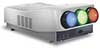
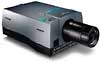
Slide 18 : Overhead projectors
Overhead projectors : Some examples of commercial products
| CRT |
LCD |
Barco
|
Nec : Short Persistence Phosphor CRT
MultiSync XG85S |
Barco |
NEC MultiSync GT series LCD projector |
| DMD / DLP |
|
|

Barco
|
Nec |
|
Barco
Barco : http://www.barco.com/projection_systems/
NEC
Nec Projectors : http://www.nec-pj.com/ind_pj.htm
or : http://www.nectech.com/presentationproducts/product_info/disc_series.cfm?divisionid=3
Nec for the Wedge :
2 NEC Multisync XG75 : CRT Projector
Video Projector to include the following: 3 picture tubes, 3 lenses,
direct projection system; can be ceiling mounted; capable of 1280 x 1024
pixels or 1500 TV lines; at least 1100 lumens at 10% peak white; horizontal
scanning frequency of 15 to 75 kHz; ability to project on fat, curved,
or tilted screens; allows input from video and computer sources; remote control
with control with control input selection, power on/off, RGB selection, brightness
control, sharpness control, hue, picture control, and volume control; includes
hardware and operators manual; two year limited warranty on parts and labor;
all necessary cables and parts for connection; setup (includes mounting to bracket,
connecting to computer, VCR, visual presenter, laserdisc player, and control
system, and setting convergence with computer and video sources.)
Slide 19 : Immersion
Immersion
From 3D on a screen to Virtual Reality
Most often we present 3-dimensional graphics on 2-dimensional displays.
What is the potential for presenting 3D information in a way that it can be
percieved as 3D?
Virtual Reality = Computer Graphics in Real Time + Immersion
+ Interaction + other perceptive feedback (touch, sound, smell...)
Terminology by K.-P. Beier
The term 'Virtual Reality' (VR) was initially coined by Jaron Lanier, founder
of VPL Research (1989). Other related terms include 'Artificial Reality' (Myron
Krueger, 1970s), 'Cyberspace' (William Gibson, 1984), and, more recently, 'Virtual
Worlds' and 'Virtual Environments' (1990s).
Today, 'Virtual Reality' is used in a variety of ways and often in a confusing
and misleading manner. Originally, the term referred to 'Immersive Virtual Reality.'
In immersive VR, the user becomes fully immersed in an artificial, three-dimensional
world that is completely generated by a computer.
Characteristics of Immersive VR
The unique characteristics of immersive virtual reality can be summarized as
follows:
- Head-referenced viewing provides a natural interface
for the navigation in three-dimensional space and allows for look-around,
walk-around, and fly-through capabilities in virtual environments.
- Stereoscopic viewing enhances the perception of depth
and the sense of space.
- The virtual world is presented in full scale and relates
properly to the human size.
- Realistic interactions with virtual objects via data
glove and similar devices allow for manipulation, operation, and control of
virtual worlds.
- The convincing illusion of being fully immersed in
an artificial world can be enhanced by auditory, haptic, and other non-visual
technologies.
- Networked applications allow for shared virtual environments
(see below).
Slide 20 : Immersion Technology
Immersion Technologies
From simple little flat screen to CAVEs

TAN Projection Technology :
http://www.tan.de/english/intro.html
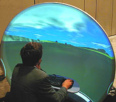
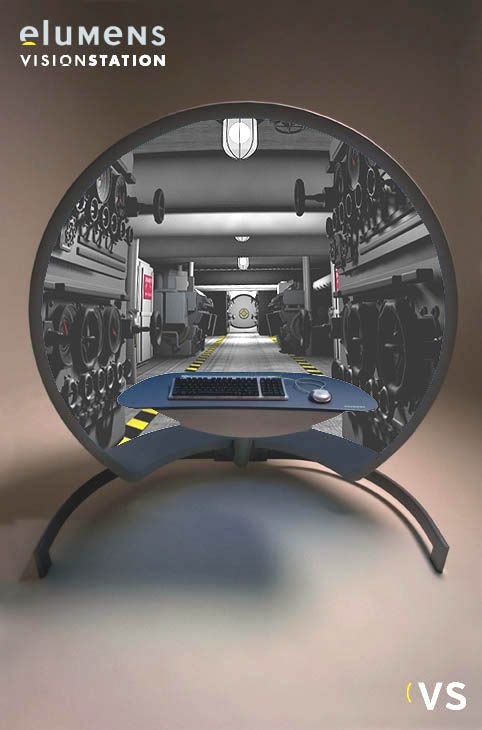
Slide 21 : Computer Screen
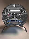
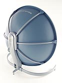
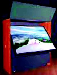
Computer Screen...
spherical one ? ....... Elumens :
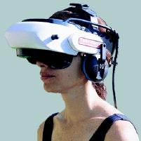
Slide 22 : Head-Mounted Display (HMD)
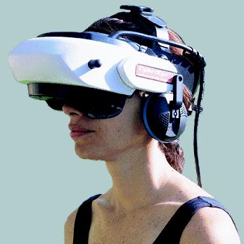
Head-Mounted Display (HMD)
 |
 |
|
UP :
Modern inexpensive HMD: The General Reality CE-200W. (Photo: General
Reality Corp.)
|
-
Two miniature dsiplays
-
Two image pipelines
-
A motion tracker
The head-mounted display (HMD) was the first device providing
its wearer with an immersive experience. Evans and Sutherland demonstrated a
head-mounted stereo display already in 1965. The EyePhone from VPL Research
was the first commercially available HMD (1989).
A typical HMD houses two miniature display screens
and an optical system that channels the images from the screens to the eyes,
thereby, presenting a stereo view of a virtual world. A motion tracker
continuously measures the position and orientation of the user's head
and allows the image generating computer to adjust the scene representation
to the current view.
As a result, the viewer can look around and walk through
the surrounding virtual environment.
Issues : Heavy
Consider carrying two displays around on your head.
+ Stereopsis is a strong
3D queue
+ Existing Technology
+ Personal Display
- Obtrusive
- Narrow FOV
(Tunnel Vision)
- Low Resolution
- Tracking
Currently the most popular 3-Dimensional (VR) display
What is the best way to get steroscopique view of two
scenes : it is by giving one differente image to each eyes
To overcome the often uncomfortable intrusiveness of a
head-mounted display, alternative concepts (e.g., BOOM
and CAVE) for immersive viewing of virtual environments
were developed.
Slide 23 : BOOM
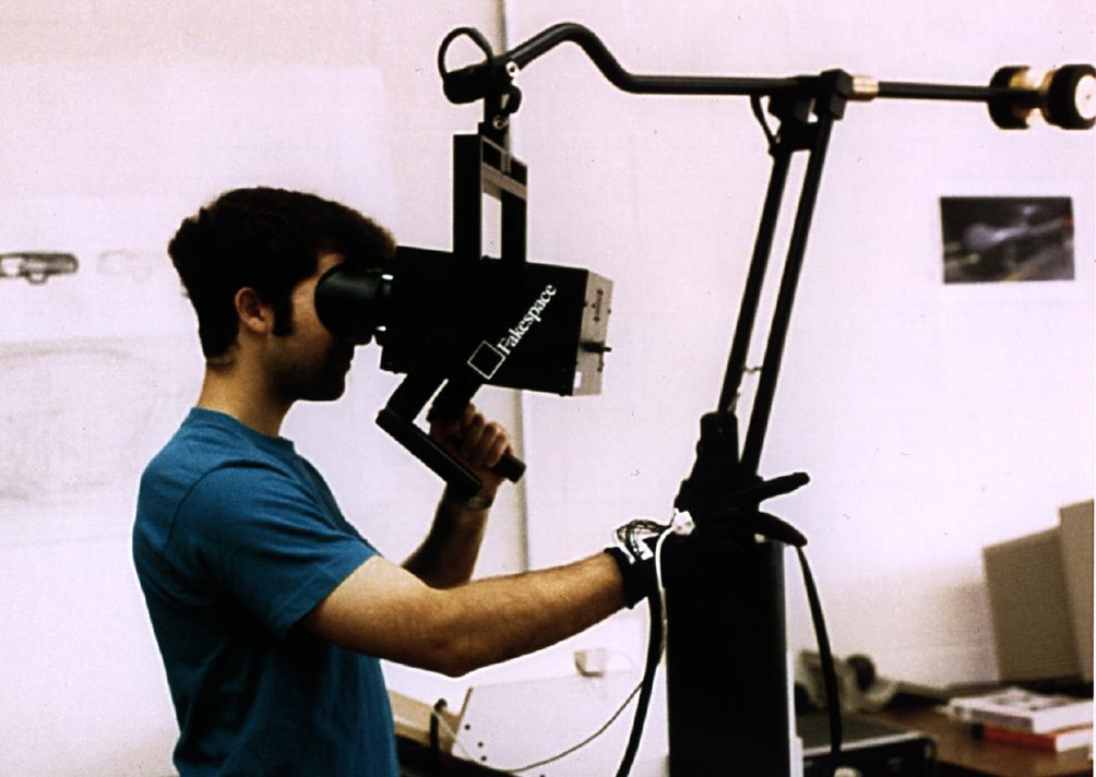
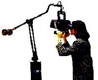
BOOM
|
|
|
|
Fakespace BOOM3C boom mounted display (Photo: Fakespace,
Inc.)
|
The BOOM (Binocular Omni-Orientation Monitor) from Fakespace
is a head-coupled stereoscopic display device.
Screens and optical system are housed in a box that
is attached to a multi-link arm. The user looks into the box through two holes,
sees the virtual world, and can guide the box to any position within the operational
volume of the device. Head tracking is accomplished via sensors in the links
of the arm that holds the box.
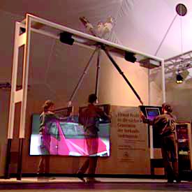 |
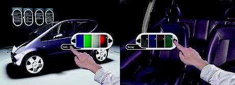 |
| Art+Com virtual car display. A counter-balanced boom constrains the display
movement as well as supports its weight. (Photo: Art+Com). |
Art+Com VR Control: Note that the display in the previous photo is a touch
screen that enables the operator to interact with the image. (Photo: Art+Com). |
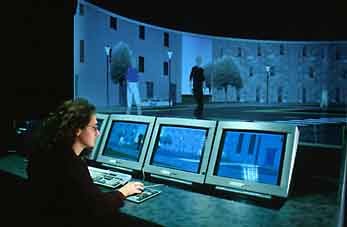
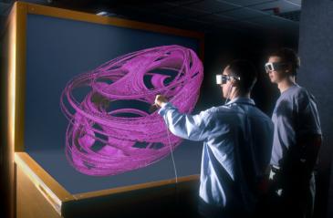
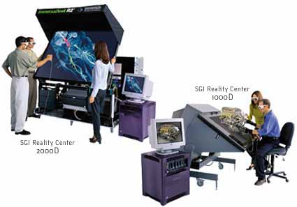
Slide 24 : Large Screen, Reality Center
Large Screen, Reality Center
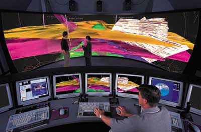
SGI France
IMMERSIA: salle de projection immersiveEn 1999, l'Irisa a fait l'acquisition
d'un équipement de projection immersive, composé d'une station
Sgi onyx2 tri-pipes et de trois projecteurs barco 1208S.
La projection est faite sur un écran semi-cylindrique d'un rayon de 3,80m,
d'un angle d'ouverture de 135 degrés et d'une hauteur de 2.38m. La projection
peut être en stéréovision à 96Hz ou 120Hz pour obtenir
une vision en relief.
Slide 25 : Workbench
Workbench
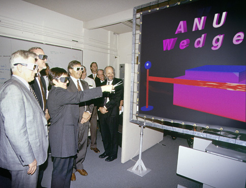
Slide 26 : Wedge
Wedge
Slide 27 : CAVE (Cave Automatic Virtual Environment)
CAVE (Cave Automatic Virtual Environment)
 |
 |
|
Schematic of an idealized Cave VR system.
Tiled rear projection stereo images appear on up to six faces of the
room in which the operator works. In practice, most Caves have three to
four faces with projections. (Image from: Cruz-Neira, Sandin, DeFanti,
Kenyon and Hart, 1992).
|
The CAVE (Cave Automatic Virtual Environment)
was developed at the University of Illinois at Chicago and provides the illusion
of immersion by projecting stereo images on the walls and floor of a room-sized
cube. Several persons wearing lightweight stereo glasses can enter and walk
freely inside the CAVE. A head tracking system continuously adjust the stereo
projection to the current position of the leading viewer.
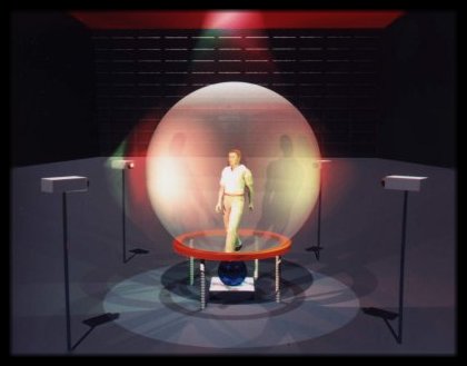
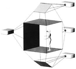
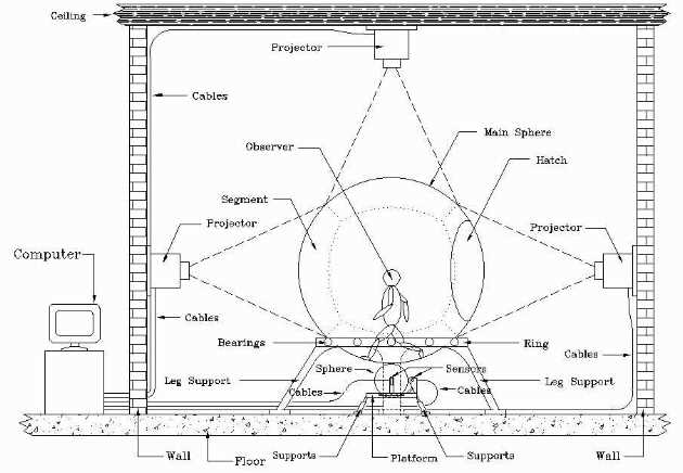
FULLY
IMMERSIVE SPHERICAL PROJECTION SYSTEM
(THE CYBERSPHERE)
Slide 28 : Following issues
Following technical issues
Projector use : projection or transmission ?
issues :
-
how to create stereo vision (3D feeling)
-
size of the device
Screen should transmit polarisation
Refreshment rate should be high
More with color and eyes subject
 SGI
SGI