eScience Lectures Notes : Transformation in 3D
Slide 1 : 1 / 19 : Three-Dimensional Transformations
Three-Dimensional Transformations
Slide 2 : 2 / 19 : Three-Dimensional Transformations
Three-Dimensional Transformations
The 3-D graphics pipeline
Rigid-body transforms
Homogeneous coordinates
Slide 3 : 3 / 19 : The 3-D Graphics Pipeline
The 3-D Graphics Pipeline
 |
-
Almost every disscusion of 3-D graphics begins here
-
Seldom are any two versions drawn the same way
-
Seldom are any two versions implemented the same way
-
Primitives are processed in a set series of steps
-
Each step forwards its result on to the next step
|
Nearly all discussions of three-dimensional computer graphics
start with the graphics pipeline. However, the notion of "the graphics
pipeline" is somewhat of a misnomer. Seldom are any two depictions, or
implementations for that matter, of a graphics pipeline identical.
The basic idea is that the processing of information in 3-dimensional computer
graphics occurs in a series of steps, where each step generates results for
the successive one.
The process starts with models that are usually described by three-dimensional
coordinates (x, y, z). The models usually define either solids or the boundaries
of object. Each of these modeling styles has a name. In solid modeling the primitives
used to describe an object have volume. In boundary representations, or B-reps,
the objects are defined in terms of their skins, or two-dimensional surfaces
that approximate the interfaces between different material types. These models
are usually defined within there own coordinate system, with their own origins
and scales of measurement.
The first step in the rendering pipeline is to transform an object from it's
own model space to a common coordinate space, called world space, in which all
objects, light sources, and the viewer coexist. This step is called the modeling
transformation stage.
The next step is an optimization. In the trivial rejection stage of the rendering
pipeline we attempt to eliminate any objects that cannot possibly be seen. This
removes some of the scene description from further processing by the rest of
the pipeline.
Next we illuminate the objects that might possibly be seen giving them colors
based on their material properties and the light sources in the scene. There
are many different ways to accomplish this illumination depending the shading
model and the surface model.
After illumination we perform another change in coordinate system that maps
the viewing position to the origin, and the viewing plane to some desired position.
This viewing transformation moves objects from world space into eye space.
Next we perform clipping of the scene's objects within a three dimensional viewing
volume called a viewing frustum. This step totally eliminates any objects (and
pieces of objects) that are not visible in the image.
In the next step we actually project the objects into two-dimensions. The transformations
is from eye-space to screen-space.
In the rasterization step we scan-convert the object into pixels. This will
often involve interpolating parameters as we go along.
But we already know how to do this (This what we've been
talking about thus far in the semester).
To summarize, almost every step in the rendering pipeline
involves a change of coordinate systems. This transformation process is central
to understanding three-dimensional computer graphics.
and it will be our starting point for our venture into
3-D computer graphics. By the way, it all about math.... but I warned you!
Slide 4 : 4 / 19 : Modeling transformations
Modeling transformations
 |
-
We starts with 3-D models defined in their own model space
-
Modeling transformations orient models within a common coordinate
system called world space
-
All objects, light sources, and the viewer live in world space
-
Trivial rejection attempts to eliminate objects that cannot
possibly be seen (an optimization)
|
Slide 5 : 5 / 19 : Illumination
Illumination
 |
-
Next we illuminate potentially visible objects
-
Object colors are determined by their material properties, and the
light sources in the scene
-
Illumination algorithm depends on the shading model and the surface
model
|
Slide 6 : 6 / 19 : Viewing Transformation
Viewing Transformation
 |
-
Another change of coordinate systems
-
Maps points from world space into eye space
-
Viewing position is transformed to the origin
-
Viewing direction is oriented along some axis
-
A viewing volume is defined
|
Slide 7 : 7 / 19 : Clipping and Projection
Clipping and Projection
 |
-
Next we perform clipping of the scene's objects againist a three
dimensional viewing volume called a viewing frustum
-
This step totally eliminates any objects (and pieces of objects)
that are not visible in the image
-
Next the objects are projected into two-dimensions
-
Transformation from eye space to screen space
|
|
View Frustum
view frustum is a semi-infinite pyramid, although the
base is usually rectangular rather than square because the screen isn't square.
In practice, however, it is normal to chop off the frustum near the point and
somewhere further down towards the base. The view frustum defines what parts
of the 3D world can be seen from the camera position when looking through a
window (usually the screen). Here's a little piccie to help clarify things a
bit :You can define a frustum using the view rectangle, the camera origin and
the near- and far-plane distances from the camera origin. This information can
then be used to make the top, bottom, left, right, near and far planes. All
the planes have their normals facing into the frustum (by convention, doesn't
matter so long as they either all point inwards or all point outwards).
Once you have these 6 planes it is easy to determine whether any given point
is inside the frustum or not - you just make sure it is above every plane. You
just test it against each plane in turn, rejecting the point if it fails at
any point in the test.
Slide 8 : 8 / 19 : Rasterization and Display
Rasterization and Display
 |
-
One last transformation from our screen-space coordinates into a
viewport coordinates
-
The rasterization step scan converts the object into pixels
-
Involve interpolating parameters as we go
-
Purely 2D operation
|
Almost every step in the rendering pipeline involves a change of coordinate
systems. Transformations are central to understanding three-dimensional computer
graphics.
Slide 9 : 9 / 19 : Rigid-Body Transformations
Rigid-Body Transformations
-
Rigid-body, or Euclidean transformations
-
Preserve the shape of the objects that they act on
-
Includes rotations and translations (just as in two dimensions)
First we begin with a representation for 3-D points. We will consider points
as column vectors. Thus, a typical point with coordinates (x, y, z) is represented
as:
 or... as ...
This is not the only possible representation. You may
encounter textbooks that consider points as row vectors. What is most important
is that you use a consistent representation.
Slide 10 : 10 / 19 : Homogenous coordinate
Homogenous coordinate
-
We don't lose anything
-
The main advantage : it is easier to compose translation and rotation
-
Everything is matrix multiplication
Slide 11 : 11 / 19 : Translations
Translations
Objects are usually defined relative to their own coordinate system. We can
translate points in space to new positions by adding offsets to their coordinates,
as shown in the following vector equation.
The following figure shows the effect of translating a teapot.
Slide 12 : 12 / 19 : Rotations
Rotations
Rotations in three-dimensions are considerably more complicated
than two-dimensional rotations. In general, rotations are specified by a rotation
axis and an angle. In two-dimensions there is only one choice of a rotation
axis that leaves points in the plane.
Right hand thumb rule
If the thumb points towards the positif axis (in the same
direction as the vector that define the rotation) then positif rotations follow
the other finger of the right hand.
A special case : Positive rotation directions about the
coordinate axes are counterclockwise, when looking toward the origin from a
positive coordinate position on each axis
Coordinate-Axes Rotations
| Around the x axis |
Around the y axis |
Around the z axis |
|
|
|
|
How to get that these matrix ? let's have a look first
at the rotation around the z axis
Slide 13 : 13 / 19 : General Three dimensional Rotations
General Three dimensional Rotations
A rotation matrix for any axis that does not coincide with a coordinate axis
can be set up as a composite transformation involving combination of translations
and the coordinate-axes rotations.
-
Translate the object so that the rotation axis passes through the coordinate
origin
-
Rotate the object so that the axis rotation coincides with one of the
coordinate axes
-
Perform the specified rotation about that coordinate axis
-
Apply inverse rotation axis back to its original orientation
-
Apply the inverse translation to bring the rotation axis back to its original
position
...
In Java 3D no way to define directly a general rotation, but at least, it is
possible to easily define a rotation around an axis that goes trough the origin
Slide 14 : 14 / 19 : Properties of the Rotation Matrix
Properties of the Rotation Matrix
Or, what is so special about a special orthogonal?
In case you missed it, a rotation matrix is a special
orthogonal matrix. By definition, a special orthogonal matrix has these properties:
AAT = I
Where AT is the transpose of A and I is the identity matrix, and
det A = 1.
This isn't really very helpful. A more helpful set of
properties is provided by Michael E. Pique in Graphics Gems (Glassner, Academic
Press, 1990):
-
R is normalized: the squares of the elements in any row or column sum
to 1.
-
R is orthogonal: the dot product of any pair of rows or any pair of columns
is 0.
-
The rows of R represent the coordinates in the original space of unit
vectors along the coordinate axes of the rotated space. (Figure 1).
-
The columns of R represent the coordinates in the rotated space of unit
vectors along the axes of the original space.
Properties 1 and 2 are useful for verifying
that a matrix is a rotation matrix. If you manipulate a matrix, and you want
to make sure that you still have a rotation matrix, sum the squares of any row
or column. If the result is not 1, then you have surely done something wrong.
If the result is 1, chances are you are on the right track.
Property 3 is useful for forward motion.
Slide 15 : 15 / 19 : Euclidean Transformations
Euclidean Transformations
For points we can combine the actions of rotation about an arbitrary axis
followed by a translation into a single 6-parameter transformation.
This set of transformations forms the algebraic group of the euclidiean transformations.
Slide 16 : 16 / 19 : More Modeling Transforms
More Modeling Transforms
It is possible to expand our repertoire of modeling transformations. We can
add Similitudes, Affines, and Projective groups of operators. However, most
of these are either not that useful in everyday practice, or they are commonly
reduced to one or two special cases, which generalize via a series of more typical
operations.
Among those transforms remaining, scales and shears are the most common:
We can generate any 3-D affine transformation using a combination of a rotation,
a scale, a shear, and a translation.
shear [n.]
(§ Homonym: sheer)
1. A machine that cuts sheet metal by passing a blade through it.
2. (Physics) A deformation of an object in which parallel planes remain parallel
but are shifted in a direction parallel to themselves; "the shear changed
the quadrilateral into a parallelogram."
Slide 17 : 17 / 19 : Other way to look at rotation
Other way to look at rotation
Roll, Pitch, Yaw
Imagine three lines running through an airplane and intersecting at right
angles at the airplane's center of gravity.
ROLL
|
PITCH
|
YAW
|
 |
 |
 |
Rotation around the front-to-back
|
Rotation around the side-to-side axis
|
Rotation around the vertical axis
|
|
|
|
|
Euler Angles
written by Ian Humphrey <I.Humphrey@sct.gu.edu.au>
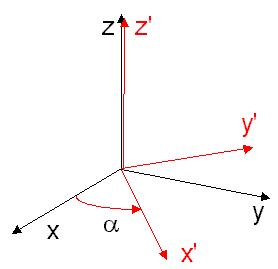
The Euler Angles (a, b, g) comprise a parametrisation
of arbitrary rotations in three-dimensional space.
The description in this document coincides with that of "Angular Momentum
in Quantum Mechanics" by Edmonds and "Angular Momentum" by Brink
and Satchler, two standard texts in the field.
The effect of Euler angle rotation R=(a, b, g) is briefly
as follows:
1. We start in frame S with cartesian axes, x, y and z.
2. We begin with a positive (anti-clockwise) rotation of magnitude a about the
z axis of S. The resulting frame is called S'.
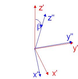
3. Next a positive rotation of magnitude b about the y' axis of frame S'. The
resulting frame is called S''.
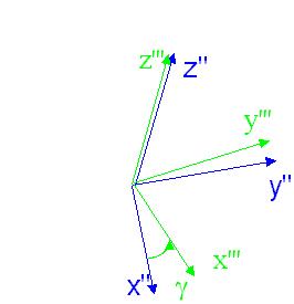
4. Finally a positive rotation of magnitude g about the z'' axis of S''. The
resulting frame is called S'''.
the phycist definition :
STEP 1:
Rotation of a about z
|
STEP 2:
Rotation of b about y'
|
STEP 3:
Rotation of g about z''
|
 |
 |
 |
Slide 18 : 18 / 19 : Some more reflexions
Some more thoughts
How to get a 3D matrix rotation around a coordinate axis
How to get a 3D matrix rotation around any axis
Difference between R.T and T.R
How to move around a central point
Why Pitch, Roll, Yaw is not the same than Yaw, Pitch, Roll...
... The Truth is Out There ...
rotation are not commutative (has anybody proved the contrary ?)
what will happen in a real plane ?
How to get the Pitch from a general Transformation ?
... that depend of the way you want to define the pitch...
Just do only incremental stuff
So, how to apply some Pitchy relative rotation whatever your initial point
is ?
Normalisation
Slide 19 : 19 / 19 : The Metaphors
The Metaphors
World in the Hand
When move the viewpoint around the centre of your Local
node, looking always towards the centre of the basis, and more precisely towards
an object placed in that centre.
This way to move around the Viewpoint is usually known
as the "world in the hand" Metaphor.
Metaphor
A Metaphor is a way to explain to users of a program how
to use its interface. You say "Do it as if you where doing something else
that you already know". The most well-known ones are of course the "Desktop"
2D Metaphor invented by Xerox, developed and popularised by Apple. It says that
to access the information available in a computer, you should have the same
behaviour as in front of a real desktop. You could open a "folder" from
which you get a "file" that you could "open", "write" into and "close"...
As 3D world is more difficult to work with than 2D one,
there are lots of metaphors around to represent the way to deal with that sort
of world.
The Flying metaphor
Flying Plane
ĀĀ Can roll, pitch and yaw the view and can move forwards (along the
-ve z' axis).
Flying Saucer
ĀĀ Can move up, down, left, right, forward and backwards relative to
local heading (ie along the x', y' and z' axes).
Flying Superman
Other Metaphors
On the Ground metaphor
The Walking metaphor
The Driving metaphor
The be yourself and move around metaphor
... the virtual reality metaphor (Pure schema)
What about interaction (required for the implementation of certain metaphors)?
Mouse Picking
A ray between the mouse and your eye
The magic wand
This is just was selection... what about manipulation of objects in the scene...
Rotation
the object in a cylinder
the object in a sphere
Translation