eScience Lectures Notes : .
Introduction to Networking over IP
Introduction
Introduction to Networking over IP
Main sources and reading : Chapter Three - A Networking Primer of "Networked Virtual Environments..." and Markus Buchhorn's presentation : "What will the New Internet Look Like"
Fundamental principles behind computer networking:
-
TCP/IP Layer Model
-
General issues
-
bandwidth
-
latency
-
reliability
-
-
Network Protocol
-
BSD Sockets Architecture
-
Sockets and Ports
-
The Internet Protocol (IP)
-
Internet Protocols for Networked VE’s:
-
TCP/IP
-
UDP/IP
-
UDP broadcasting
-
IP multicasting
-
-
Using JAVA
A Network ...
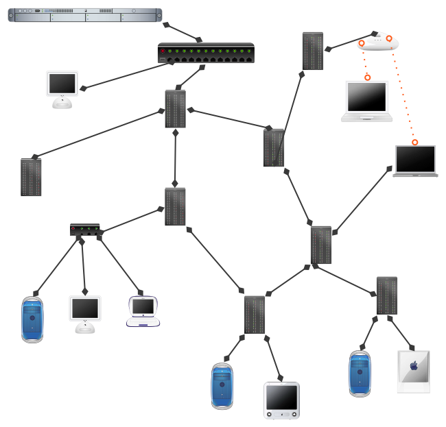
Client, server, link, node, hub, switch, router ...
See another introduction to the Internet : http://escience.anu.edu.au/lecture/comp1710/internet/index.en.html
Measures for Describing Network Behaviour
-
Network Latency (delay)
-
Network Bandwidth (rate)
-
Network Reliability (data lost)
-
Network symmetry
Network Latency
Amount of time required to transfer a bit of data from one point to another
Delay of transfer
How up to date is the information
Reasons for network latency
-
speed of light delays (~ 10 ms of delay per time zone)
-
light trough fibre : 200 k km/s, 44 835 km / 24 = 1 868 km => 9,34 ms
-
-
delays from the computers themselves
-
software (OS) and network Hardware
-
-
delays from the network : the routers (gateway) work
-
ethernet to the LAN : 10 ms
-
modem on phone system : 100 ms
-
transcontinental transfers + 60-150 ms
-
intercontinental latencies + 250-500 ms
-
Network Bandwidth
The rate at which the network can deliver data to the destination point
The amount of data that can be transmitted over a network in a fixed amount of time. Bandwidth is the fundamental networking parameter, and is usually measured in kilobits, megabits or gigabits per second (Kbps, Mbps, or Gbps).
Rate of transfer
Available bandwidth determined by wire and hardware
You may have High-Bandwidth and bad (high) latency (eg. Satellite)
A second of… |
Or live streaming |
9600bps = small email ~ 1,2 ko56kbps = web graphic ~ 7ko1Mbps = Document ~ 125 ko (cable, ADSL)10Mbps = 1 floppy disk ~ 1,25 Mo (ethernet)100Mbps = 2 MP3 songs ~ 12,25 Mo (ethernet)1Gbps = 10m CD audio ~ 125 Mo (ethernet)10Gbps = 2 CDs ~ 1,25 Go100Gbps = 2 DVDs ~ 12,5 Go |
56kbps = audio300kbps = very useful video (cable, ADSL)1500kbps, 2.2 Mbps= VHS video6Mbps = PAL video20Mbps = comp. HDTV270Mbps = raw PAL video1.5Gbps = raw HDTV1Tbps = 50,000 channels of compressed HDTV |
NB. : Mbps = 1000 x 1000 bit per second, kbps = 1000 bps, Gbps = 1000 Mbps ..... minus overhead !
MB/s (Megabytes/s) : 1024x1024 bytes per second
The standard for carriers and networks is that Mbps is
1000x1000 bits per second (and Gigabit/s is 1000x1000x1000). That's also the
transport rate, not the payload rate - so you need to allow for overheads of
whatever protocols you are using. (e.g. tcp/ip/atm/sdh - you lose a lot of payload
bandwidth that way.)
Conversely, if somebody quotes MB/s (Megabytes/s) they do usually mean 1024x1024
bytes per second.
Back in the bad old days, a 1 Megabyte floppy was 1024x1000 !
Network Bandwidth (2)
-
The current record is 6.4Tb/s…
-
ACT 300000 * 256 kbps (Transact) = 73 Gbps
-
ACT 300000 * 2.2 Mbps = 644 Gbps
-
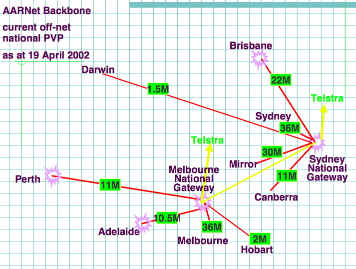
AARNET Backbone Canberra-Sydney, or Canberra-Melbourne : 18 Mbp
-
-
Bandwidth is often non symetric at the end of the network
-
TransACT : 512 / 64 kbps
-
-
No bandwidth is ‘high’ or ‘low’ – it’s just different to what you are used to.
Which depends on where you are -
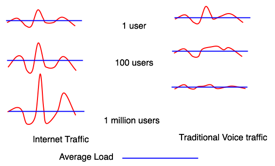
It’s not the sustained bandwidth you are catering for – it’s the peaks!
Internet traffic is fractal
See too : http://escience.anu.edu.au/lecture/comp1710/internet/evolution6.en.html
AARNET : Existing research Network in australia
Source : Markus Buchhorn's presentation : "What will the New Internet Look Like"
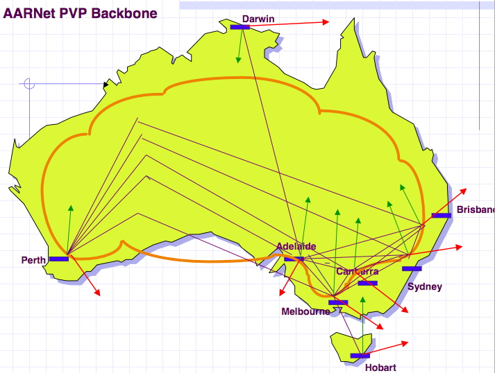
AARNET : Backbone
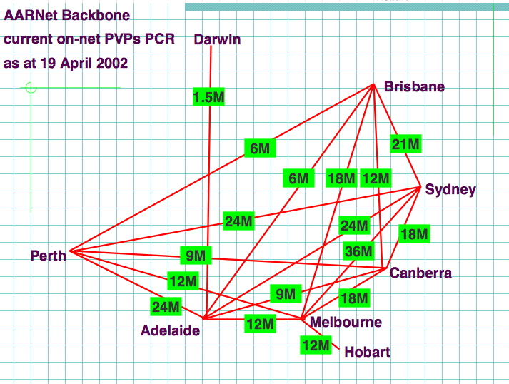
Source : Markus Buchhorn's presentation : "What will the New Internet Look Like"
AARNET : Local Peering
Source : Markus Buchhorn's presentation : "What will the New Internet Look Like"
AARNET : International Peering
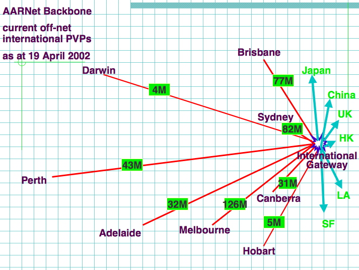
Source : Markus Buchhorn's presentation : "What will the New Internet Look Like"
The future : Grangenet and other research network / Americas
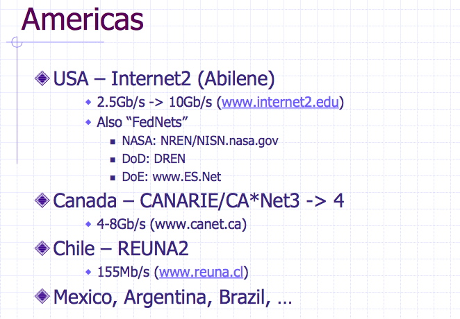
Source : Markus Buchhorn's presentation : "What will the New Internet Look Like"
The future : Grangenet and other research network / Asia-Pacific
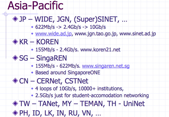
Source : Markus Buchhorn's presentation : "What will the New Internet Look Like"
The future : Grangenet Backbone
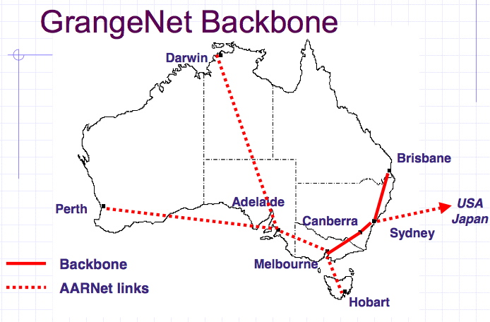
Source : Markus Buchhorn's presentation : "What will the New Internet Look Like"
The future : Grangenet Bandwidth
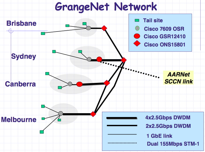
Source : Markus Buchhorn's presentation : "What will the New Internet Look Like"
Internet 2 International
or when the gap between rich and poor countries keep growing ...
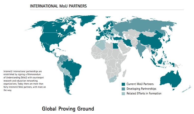
Source : http://www.internet2.edu/
Network Reliability
Measure of how much data is lost by the network during the journey
Two categories
-
Dropping - discarded by the network
-
The more common one (loss can be up to 50% packet at peak time)
-
when the queues of the router are full
-
-
Corruption - content of data packets is changed
-
1/1010, higher on wireless network
-
Use of Checksum or even error correcting codes
-
Reliability can vary widely
When reliability needed, send acknowledgement
Net Tools : How to observe the net
ifconfig : know your IP Number(s) and interface(s)
> ifconfig
lo0: flags=8049<UP,LOOPBACK,RUNNING,MULTICAST> mtu 16384
inet6 ::1 prefixlen 128
inet6 fe80::1%lo0 prefixlen 64 scopeid 0x1
inet 127.0.0.1 netmask 0xff000000
gif0: flags=8010<POINTOPOINT,MULTICAST> mtu 1280
stf0: flags=0<> mtu 1280
en0: flags=8863<UP,BROADCAST,SMART,RUNNING,SIMPLEX,MULTICAST> mtu 1500
tunnel inet -->
inet6 fe80::203:93ff:fe85:3724%en0 prefixlen 64 scopeid 0x4
ether 00:03:93:85:37:24
media: autoselect (10baseT/UTP <half-duplex>) status: active
supported media: none autoselect 10baseT/UTP <half-duplex> 10baseT/UTP
<half-duplex,hw-loopback> 10baseT/UTP <full-duplex> 10baseT/UTP
<full-duplex,hw-loopback> 100baseTX <half-duplex> 100baseTX <half-duplex,hw-loopback>
100baseTX <full-duplex> 100baseTX <full-duplex,hw-loopback> 1000baseTX
<full-duplex> 1000baseTX <full-duplex,hw-loopback> 1000baseTX <full-duplex,flow-control>
1000baseTX <full-duplex,flow-control,hw-loopback>
en1: flags=8822<BROADCAST,SMART,SIMPLEX,MULTICAST> mtu 1500
tunnel inet -->
ether 00:30:65:1d:23:48
media: autoselect (<unknown type>) status: inactive
supported media: autoselect
ppp0: flags=8051<UP,POINTOPOINT,RUNNING,MULTICAST> mtu 1492
inet 203.221.196.72 --> 203.221.196.1 netmask 0xffffff00
Net Tools : nslookup or dig : know an IP Number
> nslookup www.perthwa.com.au
Server: ns1.netspeed.com.au
Address: 203.31.48.7
Name: beast.aceonline.com.au
Address: 202.0.184.11
Aliases: www.perthwa.com.au, www.aceonline.com.au
> dig www.vuylsteker.net A
> dig www.vuylsteker.net M
Net Tools : ping : know your return time
> ping www.perthwa.com.au
PING beast.aceonline.com.au (202.0.184.11): 56 data bytes
64 bytes from 202.0.184.11: icmp_seq=0 ttl=242 time=124.208 ms
64 bytes from 202.0.184.11: icmp_seq=1 ttl=242 time=109.093 ms
64 bytes from 202.0.184.11: icmp_seq=2 ttl=242 time=101.437 ms
64 bytes from 202.0.184.11: icmp_seq=3 ttl=242 time=123.74 ms
64 bytes from 202.0.184.11: icmp_seq=4 ttl=242 time=108.126 ms
64 bytes from 202.0.184.11: icmp_seq=5 ttl=242 time=104.234 ms
^C
--- beast.aceonline.com.au ping statistics ---
7 packets transmitted, 6 packets received, 14% packet loss
round-trip min/avg/max = 101.437/111.806/124.208 ms
Net Tools : traceroute : know your way on the information highway
> traceroute www.perthzoo.wa.gov.au
traceroute to www.perthzoo.wa.gov.au (167.30.150.155), 30 hops max, 40 byte
packets
1 transact-erx.netspeed.com.au (203.56.186.1) 17.026 ms 11.022 ms 21.744 ms
2 transact-bdr.netspeed.com.au (10.192.0.10) 18.132 ms 18.632 ms 25.001 ms
3 fastethernet2-0-8.cor1.can.connect.com.au (203.63.118.194) 22.521 ms 14.861
ms 21.535 ms
4 fastethernet6-0-0.bdr1.can.connect.com.au (203.63.113.62) 14.776 ms 15.219
ms 19.298 ms
5 atm9-1-0-5.bdr2.mel.connect.com.au (203.63.112.53) 98.269 ms 33.887 ms 34.314
ms
6 acc10930-10.gw.connect.com.au (203.8.183.254) 36.203 ms 30.106 ms 43.536 ms
7 431.at-6-0-0.xr2.mel1.alter.net (210.80.32.37) 107.133 ms 36.543 ms 31.474
ms
8 so-3-1-0.xr1.mel1.alter.net (210.80.32.1) 81.341 ms 38.143 ms 44.641 ms
9 so-0-0-0.xr1.cbr2.alter.net (210.80.33.26) 85.26 ms 52.434 ms 51.065 ms
10 so-3-1-1.xr2.cbr2.alter.net (210.80.33.146) 83.295 ms 50.417 ms 46.756 ms
11 so-0-0-1.xr1.syd2.alter.net (210.80.33.5) 79.57 ms 46.565 ms 60.311 ms
12 so-6-1-0.xr2.syd2.alter.net (210.80.33.138) 87.753 ms 48.755 ms 45.465 ms
13 so-0-0-0.xr2.per1.alter.net (210.80.33.30) 100.714 ms 95.259 ms 93.371 ms
14 412.atm8-0-0.gw1.per1.alter.net (210.80.32.114) 98.995 ms 102.387 ms 172.279
ms
15 cams-per1-gw.customer.alter.net (203.166.92.26) 94.057 ms 100.024 ms 95.546
ms
16 * * *
17 * * *
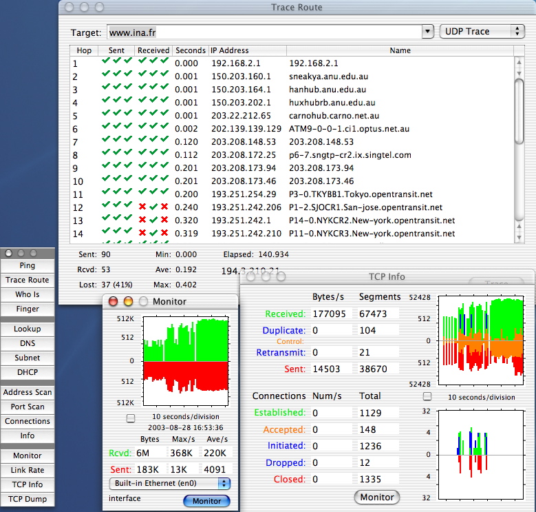
Some graphical tool to look at the network : IPNetMonitorX
Network Protocol
Describes the set of rules that two applications use to communicate to each other
Consists of three components:
-
(Packet) format
-
(Packet) semantics
-
Error behavior
(Packet) Format
-
Describes what each type of packet looks like
-
Tells the sender what to put in the packet
-
Tells recipient how to parse the inbound packet
->     ..............................
p      . Dest Add .. SrcAdd .. Type .
a      ..............................
c      . Title                      .
k      ..............................
e      . Description                .
t      .                            .
       .                            .
S      .                            .
i      .                            .
z      .                            .
e      .                            .
->     ..............................
(Packet) Semantics
Sender and recipient must agree on what the recipient can assume if it receives a particular packet
What actions the recipient should take in response to the packet
May be described using a Finite State Machine (FSM) which represents the transitions involves in the protocol.
Ex. Mail session, using the SMTP Protocol (Simple Mail Transfert Protocol)
localhost.10:29.~ pvk > telnet cs.anu.edu.au 25
Trying 150.203.164.35...
Connected to cs.anu.edu.au.
Escape character is '^]'.
220 cs.anu.edu.au ESMTP Exim 3.35 #1 Mon, 05 Aug 2002 10:28:48 +1000
Helo ruth
250 cs.anu.edu.au Hello box.anu.edu.au [150.203.160.68]
Mail From:<GDAY@MATE.au>
250 <GDAY@MATE.au> is syntactically correct
Rcpt To:<pvk@vuylsteker.net>
250 <pvk@vuylsteker.net> is syntactically correct
Data
354 Enter message, ending with "." on a line by itself
Coucou PVK
How are you ?
.
250 OK id=17bVlN-0003b4-00
QUIT
221 cs.anu.edu.au closing connection
Connection closed by foreign host.
To learn more about SMTP protocol...
Original of that page : http://www.pop-cram-spam.net/SMTP.htm
What Some Of The Stuff In An Email Header Means
There are 5 SMTP (Simple Mail Transfer Protocol) commands used to send email via a SMTP mailserver. They are:
HeloMail From:
Rcpt To:
Data
Quit
Your average, everyday SMTP transaction (sending some email) would look like this:
[the Sender connects to the Mailserver]
Mailserver says: 220 mailserver.domain.com SMTP ... Greetings
    Sender says: Helo sender.host.name
Mailserver says: 250 Nice to meet you
    Sender says: Mail From:<sender@his.address>
Mailserver says: 250 Sender ok
    Sender says: Rcpt To:<recipient@his.address>
Mailserver says: 250 Recipient ok
    Sender says: Data
Mailserver says: 354 Enter mail, end with "." on a line by itself
    Sender says: Blah, blah, blah...
    Sender says: <enter>.<enter>
Mailserver says: 250 Message accepted for delivery
    Sender says: Quit
and the SMTP transaction is complete, the email is on its way to the recipient.A mailserver doesn't have to say "ok", it can say "Eat my shorts, spammer!" if it doesn't like anything the Sender has to say to it in any of the commands, but the open relays the spammers use to send their spam always say "ok".
Helo
The Helo is *supposed* to be the host name of the computer that
has connected to the mailserver, but in the world of spam the Helo is just
whatever the spammer feels like saying. Servers that are vulnerable to
being relay-raped by spammers generally don't care what a spammer might say
in the Helo. "Helo dust-bunny-gobbler" would generally be acceptable to a
mailserver that is configured such that that it would allow spammers to
relay-rape it. In fact, it would probably be acceptable to most mailservers
running on the Internet. In general, the Helo can be anything the sender
feels like saying.
Mail From:
This is *supposed* to be the email address of the sender, but
similar to the Helo it is just what the sender *says*. Most mailservers will require the Mail From: to contain a valid domain name, but in the world of spam emanating from relay-raped servers, that isn't always the case. In any case the Mail From: is just what the sender *says*, and is totally unreliable.
Many mailservers create a Return-Path line when they recieve an email.. The email address in the Return-Path line is the email address entered with the Mail command. You may have seen references to the email "Envelope". The address entered with the Mail command is the "Envelope From" address. The "Envelope From" address is always there in the email from a mailserver point of view, but isn't always present in the received email. You won't see the "Envelope From" address unless a mailserver goes out of its way to present that address to you.
Rcpt To::This is the email address of the recipient. This will always be valid. The email address entered here is the "Envelope To" address. The "Envelope To" address often doesn't appear anywhere in an email.
Data
This is where the message itself goes. Note that Received: lines
generated by mailservers that have previously handled a message are passed
along in the Data. Note also that header lines like To: and From: etc. are
passed along in the Data, and that these lines can say anything the spammer
wants them to say.
Sometimes a spammer doesn't include lines like To: and From: in his spam. Some mailservers don't like it that these header lines aren't present and will create them based on the "Envelope". Other mailservers don't care and will pass the email along with those lines absent. The positioning of lines like To:, From:, Date:, etc. are not good indicators of header forgery.
The most commonly used mailserver software on the Internet is Sendmail. Here's an example of the relevant part of a Sendmail Received: line.
Received: from [dial45.neoms.mail.us[245.15.75.158]] (kol-dial35.asysijd.cz
[195.75.66.68]) by mail.domain.com (8.8.7/8.8.7) with SMTP ..[snip]
The spammer said "Helo [dial45.neoms.mail.us[245.15.75.158]]". Sendmail reported the actual connecting IP address (195.75.66.68), and reported the rDNS lookup of 195.75.66.68 (kol-dial35.asysijd.cz). Other mailservers do things differently, from reporting *only* the Helo to reporting the connecting IP address and explicitly saying "Helo=[dial45.neoms.mail.us[245.15.75.158]]". That's the tricky bit to sorting out spam headers, knowing what a mailserver is actually telling you in its Received: line.
So, the Sendmail format looks like this: Received: from Helo (rDNS [IP.address]) by ....
Other formats are:
Received: from rDNS (Helo) (IP.address) by ....
Received: from rDNS by ....
Received: from IP.address by ....
Received: from [IP.address] by ....
Received: from Helo by ....
and more.
For an in depth header analysis tutorial check out http://www.stopspam.org/email/headers/headers.html
For more information on SMTP, see
http://www.faqs.org/rfcs/rfc821.html
and
http://www.faqs.org/rfcs/rfc822.html
Comments Welcome
Error Behaviour
Rules about how each endpoint should respond to various error scenarios
What should I do if I don't receive an acknowledgement ?
What should the server do if the command that he has just received is not part of its official ones ? (=> send a list of available command for instance)
Same as previously : the error conditions are typically described within the same FSM that describes the normal protocol semantics
Layers of protocols, TCP/IP example
TCP/IP is made up of two acronyms, TCP, for Transmission Control Protocol, and IP, for Internet Protocol. TCP handles packet flow between systems and IP handles the routing of packets. However, that is a simplistic answer that we will expound on further.
All modern networks are now designed using a layered approach. Each layer presents a predefined interface to the layer above it. By doing so, a modular design can be developed so as to minimise problems in the development of new applications or in adding new interfaces.
The ISO/OSI protocol with seven layers is the usual reference model. Since TCP/IP was designed before the ISO model was developed it has four layers; however the differences between the two are mostly minor. Below, is a comparison of the TCP/IP and OSI protocol stacks:
| OSI Protocol Stack |
|---|
7. Application -- End user services such as email. 6. Presentation -- Data problems and data compression 5. Session -- Authentication and authorisation 4. Transport -- Guarantees end-to-end delivery of packets 3. Network -- Packet routing 2. Data Link -- Transmit and receive packets 1. Physical -- The cable or physical connection itself. |
| TCP/IP Protocol Stack. |
   5. Application   -- Authentication, compression, and end user services.
   4. Transport     -- Handles the flow of data between systems and
                       provides access to the network for applications via
                       the (BSD socket library)
   3. Network       -- Packet  routing
   2. Link          -- Kernel OS/device driver interface to the network
                       interface on the computer.
|
Major difference between the OSI and TCP/IP:
-
The application layer in TCP/IP handles the responsibilities of layers 5,6, and 7 in the OSI model.
-
The transport layer in TCP/IP does not always guarantee reliable delivery of packets as the transport layer in the OSI model does. TCP/IP offers an option called UDP that does not guarantee reliable packet delivery.
Software Components of TCP/IP
- Application Layer
- Some of the applications we will cover are SMTP (mail), Telnet, FTP, Rlogin, NFS, NIS, and LPD
- Transport Layer
- The transport uses two protocols, UDP and TCP. UDP which stands for User Datagram Protocol does not guarantee packet delivery and applications which use this must provide their own means of verifying delivery. TCP does guarantee delivery of packets to the applications which use it.
- Network Layer
- The network layer is concerned with packet routing and used low level protocols such as ICMP, IP, and IGMP. In addition, routing protocols such as RIP, OSPF, and EGP will be discussed.
- Link Layer
- The link layer is concerned with the actual transmittal of packets as well as IP to ethernet address translation. This layer is concerned with Arp, the device driver, and Rarp.
Introduction to TCP/IP Networking
Source of the information : http://userpages.umbc.edu/~jack/ifsm498d/tcpip-intro.html
Historical Overview
The strength of Unix is the built-in networking provided under Unix. In the early 1980s, the Universiy of California at Berkeley (Berkeley), had taken the original System 7 version of Unix developed at AT&T and made substantial modifications to that version of Unix. Key additions, were support for virtual memory and the initial release of TCP/IP for Unix. This release from Berkeley was known asWhether a system uses a System V or a BSD based kernel all versions of Unix now ship with 4.3 BSD networking software. Since this software was developed at Berkeley, under a US government grant, it has been available to any vendor or university at minimal cost. The TCP/IP code developed at Berkely has been ported to other operating systems, such as the DEC VMS , Macintsh, DOS, Windows, IBM CMS, IBM MVS, andmany other systems.Due to the ubiquity in the platforms where TCP/IP is available it has become the primary means for interconnecting systems in a heterogeneous computing environment.
Unix has been the platform for TCP/IP development. While Berkeley has been the main contributor countless others have contributed to the effort. This work has produced a system for networking that has proven itself over the years. Presently, there are estimated to be over 5 million systems running the TCP/IP software suite, the overwhelming majority are microcomputers. Unix has evolved as the platform to use for integrating these many different systems into something useful. As a system administrator on a Unix system it is very likely you will be involved in networking issues and need to have a basic understanding of things work.
Many vendors have provided other network on Unix systems other than (or in addition too) TCP/IP. DEC has offered a version of it's DECNET software for systems running it's version of Unix, named Ultrix. IBM also offers a version of their propreitary SNA network software on IBM AIX machines. However, the emphasis in this course will be on the TCP/IP
Introduction to TCP/IP
TCP/IP is made up of two acronyms, TCP, for Transmission Control Protocol, and IP, for Internet Protocol. TCP handles packet flow between systems and IP handles the routing of packets. However, that is a simplistic answer that we will expound on further.All modern networks are now designed using a layered approach. Each layer presents a predefined interface to the layer above it. By doing so, a modular design can be developed so as to minimize problems in the development of new applications or in adding new interfaces.
The ISO/OSI protocol with seven layers is the usual reference model. SInce TCP/IP was designed before the ISO model was developed it has four layers; however the differences between the two are mostly minor. Below, is a comparison of the TCP/IP and OSI protocol stacks:
             OSI Protocol Stack

   7. Application   -- End user services such as email.
   6. Presentation  -- Data problems and data compression
   5. Session       -- Authenication and authorization
   4. Transport     -- Gaurentee end-to-end delivery of packets
   3. Network       -- Packet routing
   2. Data Link     -- Transmit and receive packets
   1. Physical      -- The cable or physical connection itself.

            TCP/IP Protocol Stack.

   5. Application   -- Authenication, compression, and end user services.
   4. Transport     -- Handles the flow of data between systems and
                       provides access to the network for applications via
                       the (BSD socket library)
   3. Network       -- Packet  routing
   2. Link          -- Kernel OS/device driver interface to the network
                       interface on the computer.
Below are the major difference between the OSI and TCP/IP:
- The application layer in TCP/IP handles the responsibilities of layers 5,6, and 7 in the OSI model.
- The transport layer in TCP/IP does not always gaurentee reliable delivery of packets as the transport layer in the OSI model does. TCP/IP offers an option called UDP that does not gaurentee reliable packet delivery.
Software Componets of TCP/IP
- Application Layer
- Some of the applications we will cover are SMTP (mail), Telnet, FTP, Rlogin, NFS, NIS, and LPD
- Transport Layer
- The transport uses two protocols, UDP and TCP. UDP which stands for User Datagram Protocol does not gaurentee packet delivery and applications which use this must provide their own means of verifying delivery. TCP does gaurentee delivery of packets to the applications which use it.
- Network Layer
- The network layer is concerned with packet routing and used low level protocols such as ICMP, IP, and IGMP. In addition, routing protocols such as RIP, OSPF, and EGP will be discussed.
- Link Layer
- The link layer is concerned with the actual transmittal of packets as well as IP to ethernet address translation. This layer is concerned with Arp, the device driver, and Rarp.
Over the next few months we will be examining these components as we work our way up from the bottom. First, we need to get a basic upderstanding of how networks are designed and how the basic hardware used to interconnect them.
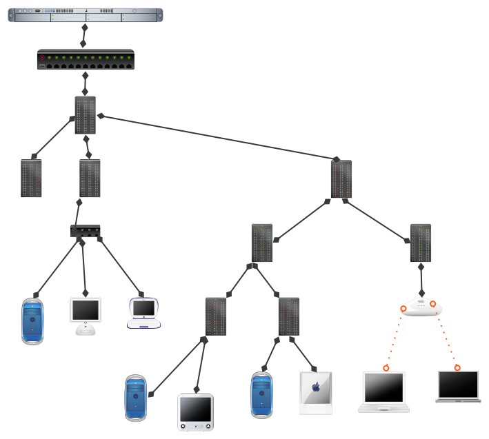
Basic Network Design
The most common form of network is Understanding the
A basic way of calculating this time limit is to look at how long a machine must monitor the network is to look at the underlying physics. By it's definition ethernet operates at a speed of 10 Mhz (10 million bits/sec). The maximum packet size is 1500 bytes (12,000 bits). Presently ethernet has a maximum lenght of 500 meters. The time required to transmit 1500 bytes over 500 meters is:
Time to transmit a packet is 12000 bits/10,000,000 bits/sec is .0012 seconds
Time to transmit a bit 500 meters is defined by the speed that electrical signals travel, which is the speed of light. This figure turns out to be :
500 meters / 60000 meters/sec which equaks .0008333 seconds
Other characteristics that define ethernet deal with the waveform that a ethernet
signal assumes. The waveform on a thick ethernet segment is 2.5 meters in lenght,
that is why stations are seperated by 2.5 meters. Ethernet Hardware Ethernet
has evolved over time. Ethernet version 2 released in 1982 was originally developed
by Xerox-Intel-Dec. In 1985 the IEEE released a new standard for ethernet. This
standard is named IEEE 802.2. In general, these two versions of ethernet can
inter-operate, however there are a few minor differences. The first difference
is that in the ethernet packet header Version 2 defined a two byte
In either specification, ethernet uses a 48 bit identifier to uniquely identify each source and destination device. A range of addresses is assigned to each manufactuer of ethernet equipment.
There are basically two categories of ethernet components, one type that passes the signal onto other devices, generally these are known as repeaters. A secondtype of device which takes the signal and regenerates the signal onto a new network, these types of devices are generally known as bridges or routers. Repeaters are useful for propagating a network signal, a signal comes in on an input port is often output to many ports.However since they add some delay to the transmittal of packets they reduce the maximum size a segment can be. However, repeaters can simplify the design of a network.
Devices such as bridges and routers, which regenerate the signal, allow you to build larger networks. Since the signal is regenerated, it becomes the responsibility of the bridge or router to gaurentee the packets arrival at the destination (or the next router or bridge). Bridges and routers work at different levels of the network. Bridges work at the ethernet frame level while routers work at the protocol level. In both cases, the bridge or router, has the property of filtering traffic and only transmitting the signal onto networks where it makes sense. Thus, in each case they have the effect of reducing unnecessary traffic.
Types of Media used with Ethernet
The IEEE 802.2 spec defines the general properties of ethernet. Subsuquent standards define how each media type will operate. At present, ethernet can be run over voice grade twisted pair (10BASE-T), thinwire coaxial cable (10Base-2), thickwire coaxial cable (10Base-5), and fiber optic cable (10Base-F). The overwhelming majority of connections made today use twisted-pair wiring. This option is now offered as standard equipment on many workstation models.Each media type has different signal properties and limits. For example, (10BASE-T) only supports one machine per segment and is limited in distance to 100 meters. Thinwire (10BASE-2) can support up to 29 stations and is limited to a maximum distance of 185 meters. Fiber optic cabling can support 1024 devices and can operate at distances up to 2 Kilometers. Thickcoaxial cable (10BASE-5) can operate up to 500 meters and support up to 1024 stations.
Trancievers often allow you to attach dis-similar devices togethor. Many machines have a 15 pin Ethernet AUI interface. Tranceivers exist which allow you to adapt the AUI interface to whatever media you have running to the desktop.
Designing Ethernet Networks
The goal in designing networks is to maximize reliability while minimizing cost. These are usually conflicting goals and tradeoffs must be made. In our environment we try to follow these guidelines:- Use twisted pair connections for all desktop connections. This is cost effective and provides an easy way to troubleshoot problems.
- Build networks that whereever possible servers and clients are on the same network.
- Use routers to build enterprise networks. Routers are more effective at isolating and controlling traffic among networks. Use bridges to seperate traffic within a network.
- Adopt the Simple Netwok Management Protocol (SNMP) as a management standard and only purchase equipment supporting that standard.
- If you are not sure of the type of cable you will be connecting it is wise to purchase machines with an AUI interface and then use transceivers to connect the machine to whatever media you have.
The BSD Sockets Architecture
Thousands of network protocols (at different layer level)
When an application sends a packet, the host must make sure that it gets sent to the right destination, and when a host receives a packet, it must make sure that it is delivered to the correct application. To achieve these two tasks, most hosts on the Internet use the Berkeley Software Distribution (BSD) Sockets network architecture to keep track of applications and network connections.
This architecture first gained wide acceptance in the Unix operating system, but today, it is implemented on virtually all of the major commercial operating systems on the market. The WinSock library used on Microsoft Windows 3.1/95/NT platforms is a derivative of the BSD interfaces [Quinn/Shute95].
Sockets and Ports
Socket: a software representation of the endpoint of a communication channel
-
can represent many different types of channels
-
IP address + UDP/TCP + port number
-
131.120.1.13, UDP, 51
-
131.120.1.13, TCP, 51
-
Port: A specific numerical identifier for an individual application
Sockets
A socket identifies several pieces of information about a communication channel:
-
Protocol: How the operating systems exchange application data
-
Destination host: The destination host address(es) for packets sent on this socket
-
Destination application ID or port: Identifies the appropriate socket on the destination host
-
Source host: Identifies which host is sending the data
- Information rarely needed
-
Local application ID or port: A 16 bit integer that identifies which application is sending data along this socket
- only if reply is needed
Example of the URL : protocol://Destination.host:destinationPort/
Port Numbers
Provide foundation of open networking
Like a set of post office box numbers for the protocol
Each type of application gets a port number
Port number + host address gives it a unique identifier to send and receive
Over 65,000 valid port numbers
OS can support many applications at once
Warcraft : What ports need to be open?
In order to connect to Battle.net, connect to others over a Local Area Network,
and allow others to connect to games you create, the following ports need to
be opened.
Diablo, Warcraft II Battle.net Edition, and StarCraft:
* Ports 6112 through 6119 TCP & UDP
Port Number Allocation
Port numbers 1 - 1023 are reserved for “well-known” applications/OS services
1024 - 10,000 are registered for certain “well-known” protocols
Example:
-
port 80 is reserved for HTTP
-
port 25 is reserved for simple mail transfer protocol
-
port 1080 is used by SOCKS (network firewall security)
See the IANA : RFC 1700 or http://www.isi.edu/in-notes/rfc1700.txt
NB. : What is a Request For Comment ?
How IP has been built, Released by the Internet Architecture Board (IAB)
Internet Protocols for Networked Virtual Environments
Common Internet Protocols
-
Internet Protocol
-
End to End connectivity between source and destination hosts(s) across heterogeneous transmission media, including fragmentation and Time to Live (TTL) services
-
-
TCP
-
Point-to-point connection with reliable transmission using acknowledgement and retransmission, providing stream-based data semantics.
-
-
UDP
-
Lightweight data transmission with "best efforts" delivery (e.g. no reliability guarantees), providing packet-based data semantics.
-
-
Broadcasting
-
"Best effort data transmission to all hosts on a LAN. Appropriate for small LANs and low-bandwidth transmissions
-
-
Multicasting
-
Efficient, "best efforts" data transmission to multiple destination hosts whose individual identities are anonymous to the transmitter. Appropriate for the Internet and large scale systems.
-
The Internet Protocol
Low-level protocol used by hosts and routers to ensure the packets travel from the source to the destination
Includes facilities for splitting the packets into small fragments
-
network links might not be able to support large packets
-
used to reconstruct packets at other end
Also includes time to live (TTL) field
-
how many network hops may transfer the packet
TCP : Transmission Control Protocol
-
Most common protocol in use today
-
Layered on top of IP referred to as TCP/IP
-
Provides illusion of point to point connection to an application running on another machine
-
Each endpoint can regard a TCP/IP connection as a bi-directional stream of bytes between two endpoints
-
Application can detect when other end of connection has gone away/disconnected
-
What You Send Is What You Get... in the Right Order
-
packets are always received by the receptor application, and in the order they were emitted by the emitter application
-
-
Use...
-
Acknowledgements and retransmits data
-
Data Checksum
-
Flow Control Procedure
-
- TCP/IP... Automatically takes care of dividing the sent data into the network packets for transmission, and it automatically extracts data from inbound packets, discards duplicate packets, and inserts the data in the correct order into the byte stream that the application reads...
UDP : User Datagram Protocol
The User Datagram Protocol (UDP) is a lightweight communication protocol
Differs from TCP in three respects:
-
connection-less transmission
- The sender and recipient of UDP data do not keep any information about the state of the communication session between the two hosts.
-
best-efforts delivery
- no attempt is made to guaranty that the data is delivered reliably and in order
-
packet-based data semantics
Does not establish peer-to-peer connections
UDP : User Datagram Protocol (2)
Sender and recipient of do not keep any information about the state of the communication session between the two hosts
Simply provides best-efforts delivery
No guarantee that data is delivered reliably or in order
Endpoints do not maintain state information about the communication,
UDP data is sent and received on a packet-by-packet basis
Datagrams must not be too big, because if they must be fragmented, some pieces might get lost in transit
UDP advantages
Simplicity ...
for the network, not the programmer
Does not include the overhead needed to detect reliability and maintain connection-oriented semantics
UDP packets require considerably less processing at the transmitting and receiving hosts
Does not maintain the illusion of a data stream
packets can be transmitted as soon as they are sent by the application instead of waiting in line behind other data in the stream; similarly, data can be delivered to the application as soon as it arrives at the receiving host instead of waiting in line behind missing data
Less heavy to manage for the OS
Many operating systems impose limits on how many simultaneous TCP/IP connections they can support.
Operating system does not need to keep UDP connection information for every peer host, UDP/IP is more appropriate for large-scale distributed systems where each host communicates with many destinations simultaneously
UDP disadvantages
Lots of possible intrusions
When a socket is receiving data on a UDP port, it will receive packets sent to it by any host, whether it is participating in the application or not
This possibility can present a security problem for some applications that
do not robustly distinguish between expected and unexpected packets
Blocking of UDP by your local net administrator
For this reason, many network firewall administrators block UDP data from being sent to a protected host from outside the security perimeter
How to Broadcast Information ?
With UDP/IP, an application can direct a packet to be sent to one other application endpoint
Could send the same packet to multiple destinations by repeatedly calling sendto() (in C) or DatagramSocket.send() (in Java)
This approach has two disadvantages:
-
Excessive network bandwidth is required because the same packet is sent over the network multiple times
-
Each host must maintain an up-to-date list of all other application endpoints who are interested in its data
UDP Broadcasting
UDP broadcasting provides a partial solution to these issues
Allows a single transmission to be delivered to all applications on a network who are receiving on a particular port
Useful for small net-VE’s
Expensive
every host on network must receive and process every broadcast packet
Not used for large or internet based VE’s (use IP Multicast)
Again subject to the usual suspicion from your local network administrator
No way to use it over the public internet
Use of a bit mask representing the subnet of hosts that should receive that message : control of the scope or range of the broadcast.
For instance, to broadcast only on the escience lab network (150.203.164.*), one should use the mask 150.203.164.255
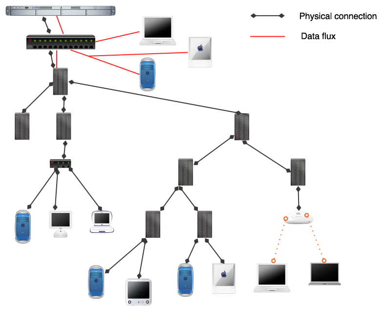
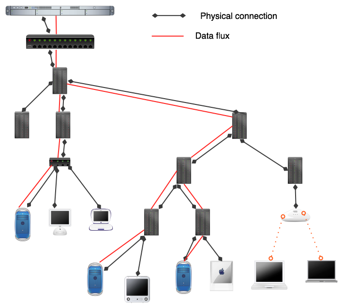
Multicasting... the Network
... Unicasting ...
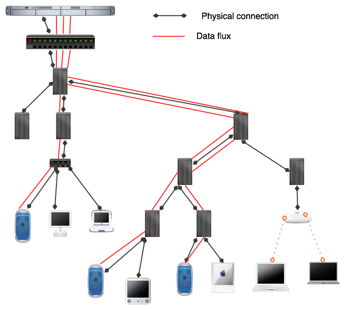
... Broadcasting ...
... Multicasting !!!
IP Multicasting
UDP broadcasting can only be used in a LAN environment
Even if no application on that host is actually interested in receiving the packet each host on the LAN must:
-
receive packet
-
process the packet
Multicasting is the solution to both of these concerns
-
Appropriate for Internet use, as well as LAN use
-
Does not impose burdens on hosts that are not interested in receiving the multicast data
Comparaison to real world news system
-
TCP/IP : equivalent to direct Mailing : Sender-controlled distribution
-
Broadcasting : equivalent to Radio
-
Multicasting : equivalent to newspaper distribution : Receiver-controlled distribution where the local distributor are related to multicast capable network routers
IP Multicasting (2)
IP addresses in the range 224.0.0.0 through 239.255.255.255 are designated as multicast addresses
-
The 224.*.*.* addresses are reserved for use by the management protocols on a LAN,
-
225.*.*.* and 232.*.*.* addresses are IANA assigned addresses
-
IANA : Internet Assigned Number Authority
-
-
Packets sent to the 239.*.*.* addresses are typically only sent to hosts within a single organisation
-
Internet-based net-VE application should therefore use one or more random addresses in the 225.*.*.* to 231.*.*.* and 233.*.*.* to 238.*.*.* range
The sender transmits data to a multicast IP address, and a subscriber receives the packet if it has explicitly joined that address
Each Multicast IP address is connected to a multicast distribution tree built by the network
To chose a free Multicast address...
-
Listen to the SAP (Session Announcement Protocol)
-
Chose an unused address and announce it using SDP (Session Description Protocol) to describe it
-
Or use the SDR (Session Directory)
IP Multicasting (3)
Rapidly emerging as the recommended way to build large-scale net-VEs over the Internet
Provides:
-
desirable network efficiency
-
allows the net-VE to partition different types of data by using multiple multicast addresses
Using a well-known multicast address, net-VE participants can announce their presence and learn about the presence of other participants
Also an appropriate technique for discovering the availability of other net-VE
resources such as terrain servers
These features make multicasting desirable even for LAN-based net-VEs.
IP Multicasting : Limitations
Limitations generally related to its infancy
Although an increasing number of routers are multicast-capable, many older routers are still not capable of handling multicast subscriptions
In the meantime, multicast-aware routers communicate directly with each other, “tunneling” data past the routers that cannot handle multicast data
Multicast on a LAN : Still Broadcasting when it comes to the bandwidth use
Comparison of the network protocol alternatives
Because most of the time, design of NVE is more about choosing which protocol for which data...
| Protocol | Strengths | Limitations | Net-VE characteristics |
|---|---|---|---|
TCP |
Guaranteed packet deliveryOrdered Packet DeliveryPacket checksum checkingTransmission flow controlUbiquitous, with many firewalls supporting outbound connections |
Only supports points to points connectivityBandwidth overheadPacket may be delayed to preserve ordering guarantees |
Virtual environments having relatively small number of hosts and limited data requirementsTypically used in client-server configuration, and over public InternetRelatively easy for the programmers |
UDP |
Packet-based data transmissionLow overheadImmediate deliveryNearly Ubiquitous, but firewalls are often problematic |
Only supports point to point connectivityNo reliability guaranteesNo ordering guaranteesPacket corruption possible |
Virtual environments having higher data requirements; used in both client-server and peer to peer configurations |
IP Broadcasting |
Same as UDP, except simultaneous delivery to multiple hosts |
Same as UDP,except scope limited to local networks |
Small-scale peer to peer net-VEs with high data requirements and time sensitive data delivery needs |
IP Multicasting |
Same as IP Broadcasting except efficient Internet-wide delivery |
Same as UDP, except only available from / to Internet hosts connected to the MBone |
Large Scale peer to peer and client server net-VEs, particularly over the Internet |
Comparison of the network protocol alternatives (2)
Use UDP... and then chose what you want get from TCP and implement it...
But not more than one or two options, or then come back to TCP/IP !
-
Packet ordering ... Serial Number
-
Common ordering ... Time stamp (+ NTP : Network Time Protocol)
-
Recovery of lost data ... Acknowledgement (Positive or negative acknowledgement scheme)
-
Flow control ... receiving application send quench packet when its queue is full)
Issue in broadcasting and Multicasting... mix of packet with other application
-
Use the human planification
-
Detect the conflict and switch to a new port number
-
Use protocol and instance magic number (a "server" decide of a common ID for the session)
-
Use encryption
JAVA TCP/IP Socket Implementation
Client Actions |
Server Actions |
|
|
JAVA TCP/IP Socket Implementation (2)
Client Actions |
INSTANTIATE SOCKET OBJECT |
|
Instantiating a socket creates a socket and connects it to the server Two common constructors
|
import java.net.Socket;
import java.io.IOException;
import java.io.DataInputStream;
import java.io.DataOutputStream;


Socket sock;	// Declare the socket
				// Instantiate the socket using host name and port number
try {
	sock = new Socket("ephebe.anu.edu.au", 13214);
	//	or...Retrieve the host’s internet address ...
	//	InetAddress addr = InetAddress.getByName("150.203.164.3");
	//	sock = new Socket(addr, 13214);}
catch(IOException ioe) {
	System.out.println("Error opening socket: " + ioe.getMessage());
	return;
}
JAVA TCP/IP Socket Implementation (3)
Client Actions |
Communicate with server |
|
|
try{
		//  Instantiate an output stream tied directly to the socket
	DataOutputStream oStream = new DataOutputStream(sock.getOutputStream());
		//  write a string and an int to the output stream,
		//	i.e. transmit them to the server
	oStream.writeUTF("Hello!");
	oStream.writeInt(3);
	oStream.flush(); //tell java to empty the stream right now (= send the information)
}
catch(IOException ioe) {
	System.out.println("Write error: " + ioe.getMessage());
}
JAVA TCP/IP Socket Implementation (4)
Client Actions |
Close the socket |
|
|
try	{
	sock.close();
}
catch(IOException ioe) {
	System.out.println("Close error: " + ioe.getMessage());
}

// Again, close() needs to be called on both sides of the connection, and the server should
// also be sure to close() the ServerSocket when it no longer wishes to accept client
// connections.
JAVA TCP/IP Socket Implementation (5)
Server Actions |
Instantiate a ServerSocket object |
|
|
import java.net.ServerSocket;
import java.net.Socket;
import java.io.IOException;
import java.io.DataInputStream;
import java.io.DataOutputStream;

ServerSocket acceptSock;                   // Declare the ServerSocket

//  Instantiate a ServerSocket using constructor that takes only the port number
try {
	acceptSock = new ServerSocket(13214);
}

catch(IOException ioe) {
	System.out.println("Error opening server socket: " + ioe.getMessage());
	return;
}
JAVA TCP/IP Socket Implementation (6)
Server Actions |
Receive connections from clients |
|
|
Socket sock;	// Declare a socket to represent the connection to a
				// specific client, i.e. the socket client and server will
				// communicate over

//  Call accept() on the ServerSocket to receive client connections,
//  when a connection is received a new socket is returned over which
//  the client and server will communicate

while(true) {
	try {
		sock = acceptSock.accept();
	}
	catch(IOException ioe) {
 		System.out.println("accept error: " + ioe.getMessage());
		break;
 	}
	/* ... Process client connection ... */
}
// Only break out of while loop if there was an error
JAVA TCP/IP Socket Implementation (7)
For More see Sun Web site : http://java.sun.com/docs/books/tutorial/networking/index.html
Server Actions |
Communicate with clients |
|
|
try{
	//  Instantiate an input stream tied directly to the socket
	DataInputStream iStream = new DataInputStream(sock.getInputStream());

	//  Read a string and an int from the input stream, i.e from the socket
	//  You need to know the Semantics of the used protocol !
	String helloString = iStream.readUTF();
	int three = iStream.readInt();
}
catch(IOException ioe) {
	System.out.println("Read error: " + ioe.getMessage());
}

try{
    sock.close();
}
catch(IOException ioe) {
	System.out.println("Close error: " + ioe.getMessage());
}